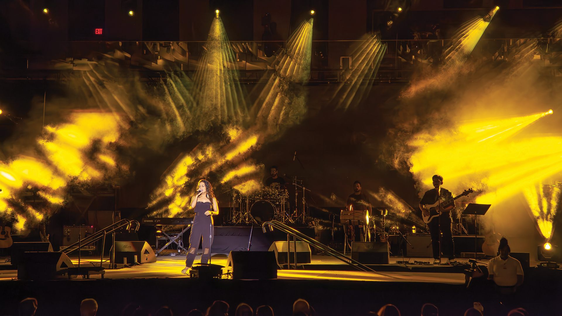
Audio delay across large venues is the quiet destroyer of live event credibility. The audience member standing 60 meters from the stage who hears sound arriving first from the delay speaker overhead, then a fraction of a second later from the main PA, does not consciously diagnose the problem as a time alignment error. They simply feel that something is wrong — that the sound is muddy, that the performer’s mouth isn’t matching the audio. Solving that perception problem requires a rigorous understanding of acoustic propagation, digital system latency, and the measurement tools that bridge both.
The Physics: Speed of Sound Is Immutable
Sound travels through air at approximately 343 meters per second at 20°C. This means that for every 10 meters of distance between a speaker and a listener, the acoustic signal arrives approximately 29 milliseconds late. A delay speaker array hung 30 meters from the main PA must have its signal delayed by 87ms relative to the main system for the two sources to arrive simultaneously. Failing to apply this delay means the louder, closer delay speaker arrives first, and the brain perceives the main PA’s delayed arrival as a confusing smear. This is the Haas effect working against the production — the precedence effect that causes the ear to localize sound to the first arriving source, even when a louder source follows milliseconds later.
Digital System Latency: The Hidden Addend
In the analog era, the only delay variable was acoustic propagation. In the digital era, every device in the signal chain introduces processing latency. A Dante-networked system operating at 48kHz with 1ms packet time adds 1ms of latency per network hop. A digital console like the Avid S6L introduces approximately 0.7–1.2ms of input-to-output latency. An amplifier with onboard DSP like the Lab.gruppen PLM 20000Q adds another 0.5–1.5ms. The audio engineer setting delay times in a PA system must account for the total system latency at every point in the chain, not just the acoustic distance.
Measurement Tools: Working from Data
Time alignment is not an art — it is a measurement exercise. The professional standard for PA time alignment measurement is to use a dedicated audio analysis platform: Rational Acoustics Smaart v9, Meyer Sound SIM3, or d&b ArrayCalc. These platforms generate a broadband test signal, capture it via a calibrated measurement microphone, and produce a transfer function measurement that shows both the frequency response and the impulse response of the system at the measurement position. The impulse response reveals exactly when sound is arriving and from which sources — allowing the engineer to identify comb filtering signatures caused by misaligned delays with sub-millisecond precision.
Setting Delay Accurately: The Process
The professional workflow for setting delay speaker timing begins with a measurement microphone positioned in the overlap zone between the main PA and the delay speaker. Smaart’s delay locator function measures the acoustic distance from both sources to the microphone position, calculates the difference, and provides a suggested delay offset. The engineer applies that offset to the delay speaker in the DSP — either in the amplifier’s onboard processing, or in a dedicated signal processor like the Lake LM 44 or BSS Audio BLU-100. A small additional offset of 1–5ms is often added beyond perfect time alignment, nudging the precedence effect to favor the main PA while keeping the delay speaker acoustically coherent.
Multi-Zone Venues and the Cascading Delay Challenge
In multi-zone venues — a sports arena with concourse speakers, hospitality areas, and a DJ booth simultaneously running off the main FOH mix — the cascading delay chain becomes complex quickly. The concourse speakers need not just the main-to-delay offset but also a delay that accounts for their physical position behind the farthest audience seat in the main bowl. A correct multi-zone delay map calculates each zone’s delay independently, referenced to the acoustic arrival time of the main PA at the nearest boundary of that zone. Modern PA processors like the QSC Q-SYS Core allow the engineer to program and label all zone delays in a single software environment.
Temperature, Humidity, and Real-Time Compensation
Speed of sound is not a fixed constant on a show day. A 10°C temperature increase accelerates sound by approximately 6 m/s — enough to shift the time alignment of a 60-meter delay throw by over a millisecond. Real-time temperature compensation algorithms are available in systems like Meyer Sound Galileo GALAXY and Linea Research 44M20D, which automatically adjust internal delay times based on measured ambient temperature, keeping the system in alignment as conditions change throughout the day. An outdoor festival that starts its sound check at 11am in 18°C air and reaches show time at 8pm in 28°C air will have measurably different delay requirements by the time the headliner walks on.
Common Mistakes and How to Avoid Them
The most frequent delay alignment errors in professional practice are: applying delay only to the speaker’s acoustic distance without accounting for total system latency; setting delays from acoustic calculations without measurement verification; failing to re-verify alignment after a gain change or system configuration update; and misidentifying which source is arriving first in an overlap zone due to reflections contaminating the measurement. Eliminating all four requires a rigorous measurement workflow using Smaart or equivalent, and the discipline to re-measure after every significant system change, not just at initial setup. Time alignment is the least glamorous task in live audio system engineering. It is also one of the most audibly impactful.